


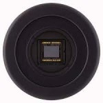


Moravian Camera C1-1500 Mono CMOS Astrophoto Guiding&Imaging Camera

- Stok: Ön Sipariş
- Stok Kodu: MI-C1-1500
| Model | Moravian Camera C1-1500 Mono CMOS Astrophoto Guiding&Imaging Camera |
| Marka | Moravian Instruments |
| Item Code | MI-C1-1500M |
| Sensor | Sony IMX273 CMOS |
| Colour filter | No |
| Resolution | 1456 x 1088 pixels |
| Pixel Size | 3.45 x 3.45 µm |
| Imaging Area | 5.02 x 3.75 mm |
| Shutter | Global Shutter (Not include internal mechanical shutter) |
| Digitization | 8-bit and 12-bit |
| Shortest Exposue Time | 125 μs |
| Diagonal size | 6.27 mm |
| Interface | USB 3.0 |
| Download time | Appr. 0.05s with USB3.0 host |
| Dimensions | 57x57x48 mm (only camera head) |
| Cooling | Passive fan cooling |
| Back Focal Distance | 12.5 mm for 1/32 UN thread (CS-mount compatible) |
| 18.5 mm for M42 × 0.75 thread (T-mount) | |
| Camera Head Weight | 215 gr |
| Adapters | CS-thread lens adapter, CS to 1.25'' telescope adapter |
The C1 series CMOS cameras were designed to be small, lightweight imagers for Moon and planets and for automatic telescope guiding. With proper image calibration, C1 cameras provide surprisingly good results also in entry-level deep-sky imaging. The used CMOS sensors response to light is linear up to very close to saturation point, so, C1 cameras can be used for scientific applications like variable star research, too.
C1 cameras with Sony IMX sensors supporting 12-bit digitization only. As the 12-bit read mode is always used for long-exposure applications (astronomical photography, scientific research) either way, lower theoretical download time in 8-bit mode brings no limitations for real-world scenarios. All other parameters being same (sensor size, resolution, pixels size, noise, …), lower price of these cameras may be then very attractive.
To operate the camera, you need a computer which:
1-Is compatible with a PC standard and runs modern 32 or 64-bit Windows operating system.
2-Is compatible with a PC standard and runs 32 or 64-bit Linux operating system.
Remark:
Drivers for 32-bit and 64-bit Linux systems are provided, but the SIPS camera control and image processing software, supplied with the camera, requires Windows operating system.
3-Support for x64 based Apple Macintosh computers is also included.
Remark:
Only certain software packages are currently supported on Mac.
Camera Electronics
CMOS camera electronics primary role, beside the sensor initialization and some auxiliary functions, is to transfer data from the CMOS detector to the host PC for storage and processing. So, as opposite to CCD cameras, CMOS camera design cannot influence number of important camera features, like the dynamic range (bit-depth of the digitized pixels).
Download speed
As already noted, there are two lines of C1 camera series, differing in the used sensor. The first series offers four different read modes:
8-bit slow mode with ~132 MPx/s digitization speed
12-bit slow mode with ~72 MPx/s digitization speed
8-bit fast mode with ~263 MPx/s digitization speed
12-bit fast mode with ~132 MPx/s digitization speed
Remark:
The slow variant of both read modes can be used to slightly lower the amount of heat generated by the sensor, as the communication interface operates at half speed compared to fast mode. Also, when the camera is connected using USB 2.0 interface, fast read mode provides data at higher speed than the USB 2.0 can handle and thus causes more interruptions of image digitization process.
Camera gain
Sensors used in C1 cameras offer programmable gain from 0 to 24 dB, which translates to the output signal multiplication from 1× to 15.9×. Gain can be set with 0.1 dB step.
Remark:
Note the C1 camera firmware supports only analog gain, which means real amplification of the signal prior to its digitization. The used sensors support also digital gain control, which is only numerical operation, bringing no real benefit for astronomical camera. Any such operation can be performed later during image processing if desired.
Conversion factors and read noise
Generally, many sensor characteristics depend on the used gain. So, we provide two list of parameters for both minimal and maximal gain.
Camera/sensor parameters for minimal gain 0 dB (1×):
Full well capacity 9000 e-
Conversion factor 2.2 e-/ADU
Read noise (12 bit) 1.8 e- RMS
Camera/sensor parameters for maximal gain 24 dB (15.9×):
Full well capacity 820 e-
Conversion factor 0.2 e-/ADU
Read noise (12 bit) 1.2 e- RMS
Remark:
Please note the values stated above are not published by sensor manufacturer, but determined from acquired images. Results may slightly vary depending on particular sensor and other factors (e.g. sensor temperature), but also on the software used to determine these values.
Exposure control
C1 cameras are capable of very short exposures. The shortest exposure time is 125 μs (1/8000 of second). This is also the step, by which the exposure time is expressed. So, the second shortest exposure is 250 μs etc.
Long exposure timing is controlled by the host PC and there is no upper limit on exposure time. In reality the longest exposures are limited by saturation of the sensor either by incoming light or by dark current (see the following sub-chapter).
Sensor Cooling
Dark current is an inherent feature of all silicone circuits. It is called “dark”, because it is generated regardless if the sensor is exposed to light or not. Dark current, injected into individual pixels, appear in image as noise. The longer exposure, the greater amount of noise is present in every image. As it is generated by random movement of particles, it depends on the temperature exponentially (this is why the noise generated by dark current is also denoted “thermal noise”). Typically, lowering the sensor temperature by 6 or 7 °C halves the dark current.
While the C1 cameras are not equipped with active thermo-electric (Peltier) cooling, they are still equipped with a small fan, exchanging the air inside the camera body. What's more, a small heat sink is located directly on the sensor (with the exception of the C1-1500 model, which sensor is too small for heat sink) to remove as much heat as possible. So, the C1 sensor cannot be cooled below the ambient temperature, but its temperature is kept as close to environment as possible. Compared to closed designs, the sensor temperature in the C1 camera can be up to 10°C lower and resulting dark current may be less than half. The fan operation can be controlled from the software. SIPS directly offers a slider controlling fan in the “Cooling” tab of the main camera control tool window. Camera drivers for other software must rely on driver configuration dialog box to control fan. With fan off, sensor temperature quickly rises more than 10 °C above ambient. Turning fan on lowers the temperature by 5 °C or more.
Standard 6-pin Autoguider Port is located beside the USB3 port on the top side of C1 camera
The Autoguider port follows the de-facto standard introduced by SBIG ST-4 autoguider. The pins have the following functions:
1 R.A. + (Right)
2 Dec + (Up)
3 Dec – (Down)
4 R.A. – (Left)
5 Common (Ground)
6 Not connected
Telescope/lens adapters
C1 cameras are supplied with two types of telescope/lens adapters:
*Adapter with 1/32 UN thread and 12.5 mm Back Focal Distance (CS-mount).
**Adapter with M42 × 0.75 thread (T-thread) and 18.5 mm Back Focal Distance. This adapter also contains inner thread 1/32 UN with 12.5 mm BFD (CS-mount).
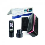
C1 camera with T-thread (M42 × 0.75) adapter (left) and with CS-mount adapter (right)
CS-mount it compatible with vast number of CCTV lenses. If C-mount lens has to be used (with 17.5 mm Back Focal Distance), simple 5 mm thick adapter ring can be used.
Warning:
If the C1 camera should be used with OAG for cooled Cx or Gx cameras, short 10 mm C-to-1.25” barrel adapter has to be used. This adapter, shipped with respective OAG, is fully compatible with C1 camera.
Note the C1 camera with M42 × 0.75 (T-thread) adapter cannot be used with OAG, despite the short CS-to-1.25" barrel adapter can be attached to it. The large-diameter M42 adapter interferes with screws fixing the camera in the OAG guider port. This is why C1 variant with CS-mount only adapter is still supplied.
C-to-1.25” barrel adapter, compatible with standard 1.25” eyepieces, is included into camera package. So, the C1 camera can be easily mounted into virtually every astronomical telescope instead of an eyepiece.
The T-mount interface (also known as T-thread adapter) is defined by thread dimensions M42 × 0.75 as well as by 55 mm Back focal Distance. T-thread adapter for C1 cameras does not comply to the second parameter, its BFD is only 18.5 mm. The 55 mm BFD is not required in all applications and keeping such relatively large BFD would make the adapter quite bulky.
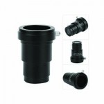
Still, an extension tube with male M42 × 0.75 thread is available. This extension tube converts the C1 camera BFD to 55 mm, required by numerous focal-reducers, field-flatteners, coma-correctors and other optical elements.
There are two variants of the 55 mm BFD extension tubes available:
Extension tube with M42 × 0.75 (T-thread) on the telescope side.
Extension tube with larger M48 × 0.75 thread on the telescope side.
Also, extension tubes with bayonet interfaces for standard photographic lenses are available:
Extension tube with Nikon bayonet adapter.
Extension tube with Canon EOS bayonet adapter.
| Model | Moravian Camera C1-1500 Mono CMOS Astrophoto Guiding&Imaging Camera |
| Marka | Moravian Instruments |
| Item Code | MI-C1-1500M |
| Sensor | Sony IMX273 CMOS |
| Colour filter | No |
| Resolution | 1456 x 1088 pixels |
| Pixel Size | 3.45 x 3.45 µm |
| Imaging Area | 5.02 x 3.75 mm |
| Shutter | Global Shutter (Not include internal mechanical shutter) |
| Digitization | 8-bit and 12-bit |
| Shortest Exposue Time | 125 μs |
| Diagonal size | 6.27 mm |
| Interface | USB 3.0 |
| Download time | Appr. 0.05s with USB3.0 host |
| Dimensions | 57x57x48 mm (only camera head) |
| Cooling | Passive fan cooling |
| Back Focal Distance | 12.5 mm for 1/32 UN thread (CS-mount compatible) |
| 18.5 mm for M42 × 0.75 thread (T-mount) | |
| Camera Head Weight | 215 gr |
| Adapters | CS-thread lens adapter, CS to 1.25'' telescope adapter |
The C1 series CMOS cameras were designed to be small, lightweight imagers for Moon and planets and for automatic telescope guiding. With proper image calibration, C1 cameras provide surprisingly good results also in entry-level deep-sky imaging. The used CMOS sensors response to light is linear up to very close to saturation point, so, C1 cameras can be used for scientific applications like variable star research, too.
C1 cameras with Sony IMX sensors supporting 12-bit digitization only. As the 12-bit read mode is always used for long-exposure applications (astronomical photography, scientific research) either way, lower theoretical download time in 8-bit mode brings no limitations for real-world scenarios. All other parameters being same (sensor size, resolution, pixels size, noise, …), lower price of these cameras may be then very attractive.
To operate the camera, you need a computer which:
1-Is compatible with a PC standard and runs modern 32 or 64-bit Windows operating system.
2-Is compatible with a PC standard and runs 32 or 64-bit Linux operating system.
Remark:
Drivers for 32-bit and 64-bit Linux systems are provided, but the SIPS camera control and image processing software, supplied with the camera, requires Windows operating system.
3-Support for x64 based Apple Macintosh computers is also included.
Remark:
Only certain software packages are currently supported on Mac.
Camera Electronics
CMOS camera electronics primary role, beside the sensor initialization and some auxiliary functions, is to transfer data from the CMOS detector to the host PC for storage and processing. So, as opposite to CCD cameras, CMOS camera design cannot influence number of important camera features, like the dynamic range (bit-depth of the digitized pixels).
Download speed
As already noted, there are two lines of C1 camera series, differing in the used sensor. The first series offers four different read modes:
8-bit slow mode with ~132 MPx/s digitization speed
12-bit slow mode with ~72 MPx/s digitization speed
8-bit fast mode with ~263 MPx/s digitization speed
12-bit fast mode with ~132 MPx/s digitization speed
Remark:
The slow variant of both read modes can be used to slightly lower the amount of heat generated by the sensor, as the communication interface operates at half speed compared to fast mode. Also, when the camera is connected using USB 2.0 interface, fast read mode provides data at higher speed than the USB 2.0 can handle and thus causes more interruptions of image digitization process.
Camera gain
Sensors used in C1 cameras offer programmable gain from 0 to 24 dB, which translates to the output signal multiplication from 1× to 15.9×. Gain can be set with 0.1 dB step.
Remark:
Note the C1 camera firmware supports only analog gain, which means real amplification of the signal prior to its digitization. The used sensors support also digital gain control, which is only numerical operation, bringing no real benefit for astronomical camera. Any such operation can be performed later during image processing if desired.
Conversion factors and read noise
Generally, many sensor characteristics depend on the used gain. So, we provide two list of parameters for both minimal and maximal gain.
Camera/sensor parameters for minimal gain 0 dB (1×):
Full well capacity 9000 e-
Conversion factor 2.2 e-/ADU
Read noise (12 bit) 1.8 e- RMS
Camera/sensor parameters for maximal gain 24 dB (15.9×):
Full well capacity 820 e-
Conversion factor 0.2 e-/ADU
Read noise (12 bit) 1.2 e- RMS
Remark:
Please note the values stated above are not published by sensor manufacturer, but determined from acquired images. Results may slightly vary depending on particular sensor and other factors (e.g. sensor temperature), but also on the software used to determine these values.
Exposure control
C1 cameras are capable of very short exposures. The shortest exposure time is 125 μs (1/8000 of second). This is also the step, by which the exposure time is expressed. So, the second shortest exposure is 250 μs etc.
Long exposure timing is controlled by the host PC and there is no upper limit on exposure time. In reality the longest exposures are limited by saturation of the sensor either by incoming light or by dark current (see the following sub-chapter).
Sensor Cooling
Dark current is an inherent feature of all silicone circuits. It is called “dark”, because it is generated regardless if the sensor is exposed to light or not. Dark current, injected into individual pixels, appear in image as noise. The longer exposure, the greater amount of noise is present in every image. As it is generated by random movement of particles, it depends on the temperature exponentially (this is why the noise generated by dark current is also denoted “thermal noise”). Typically, lowering the sensor temperature by 6 or 7 °C halves the dark current.
While the C1 cameras are not equipped with active thermo-electric (Peltier) cooling, they are still equipped with a small fan, exchanging the air inside the camera body. What's more, a small heat sink is located directly on the sensor (with the exception of the C1-1500 model, which sensor is too small for heat sink) to remove as much heat as possible. So, the C1 sensor cannot be cooled below the ambient temperature, but its temperature is kept as close to environment as possible. Compared to closed designs, the sensor temperature in the C1 camera can be up to 10°C lower and resulting dark current may be less than half. The fan operation can be controlled from the software. SIPS directly offers a slider controlling fan in the “Cooling” tab of the main camera control tool window. Camera drivers for other software must rely on driver configuration dialog box to control fan. With fan off, sensor temperature quickly rises more than 10 °C above ambient. Turning fan on lowers the temperature by 5 °C or more.
Standard 6-pin Autoguider Port is located beside the USB3 port on the top side of C1 camera
The Autoguider port follows the de-facto standard introduced by SBIG ST-4 autoguider. The pins have the following functions:
1 R.A. + (Right)
2 Dec + (Up)
3 Dec – (Down)
4 R.A. – (Left)
5 Common (Ground)
6 Not connected
Telescope/lens adapters
C1 cameras are supplied with two types of telescope/lens adapters:
*Adapter with 1/32 UN thread and 12.5 mm Back Focal Distance (CS-mount).
**Adapter with M42 × 0.75 thread (T-thread) and 18.5 mm Back Focal Distance. This adapter also contains inner thread 1/32 UN with 12.5 mm BFD (CS-mount).
C1 camera with T-thread (M42 × 0.75) adapter (left) and with CS-mount adapter (right)
CS-mount it compatible with vast number of CCTV lenses. If C-mount lens has to be used (with 17.5 mm Back Focal Distance), simple 5 mm thick adapter ring can be used.
Warning:
If the C1 camera should be used with OAG for cooled Cx or Gx cameras, short 10 mm C-to-1.25” barrel adapter has to be used. This adapter, shipped with respective OAG, is fully compatible with C1 camera.
Note the C1 camera with M42 × 0.75 (T-thread) adapter cannot be used with OAG, despite the short CS-to-1.25" barrel adapter can be attached to it. The large-diameter M42 adapter interferes with screws fixing the camera in the OAG guider port. This is why C1 variant with CS-mount only adapter is still supplied.
C-to-1.25” barrel adapter, compatible with standard 1.25” eyepieces, is included into camera package. So, the C1 camera can be easily mounted into virtually every astronomical telescope instead of an eyepiece.
The T-mount interface (also known as T-thread adapter) is defined by thread dimensions M42 × 0.75 as well as by 55 mm Back focal Distance. T-thread adapter for C1 cameras does not comply to the second parameter, its BFD is only 18.5 mm. The 55 mm BFD is not required in all applications and keeping such relatively large BFD would make the adapter quite bulky.
Still, an extension tube with male M42 × 0.75 thread is available. This extension tube converts the C1 camera BFD to 55 mm, required by numerous focal-reducers, field-flatteners, coma-correctors and other optical elements.
There are two variants of the 55 mm BFD extension tubes available:
Extension tube with M42 × 0.75 (T-thread) on the telescope side.
Extension tube with larger M48 × 0.75 thread on the telescope side.
Also, extension tubes with bayonet interfaces for standard photographic lenses are available:
Extension tube with Nikon bayonet adapter.
Extension tube with Canon EOS bayonet adapter.


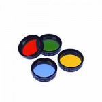
 FILTER, 36 MM DIAMETER UNMOUNTED")


